
Development of a Conductive Ink Toolkit for Educational Purposes
Project Description
This project discusses the design and development of a toolkit interface to enable the construction of interactive paper tools. Our work for this project consisted of three main parts. The first part was the development of a software toolkit, or the graphical user interface. This toolkit allows the user to create a drawing using different components and print out interactive learning tools. The second part was the design of the hardware architecture, or the physical user interface. An Arduino device was flexible enough so that it was easily configured to work with various interactive components and, for this project, the output of the interaction responded with LED lights. Lastly, the project sought feedback on the interaction of both the graphical and physical interfaces from Electrical Engineering, Human-Computer Interaction, and Industrial Design experts.
Project Details
Course CS7470 Mobile and Ubiquitous Computing
Date May 2013
Skills Arduino, Illustrator, Conductive Ink Printers
Role Project lead, all physical prototyping

Conductive Ink Toolkit UI
The software toolkit, which was developed using Java, provides a graphical user interface that enables the users to drag and drop various interactive components. The interactive components can work as buttons, potentiometers, circuits, etc. There are four different tabs the user can chose their components from. These are reading, writing, arithmetic and games, which were the subject areas we decided to focus on. Once the user has completed creating their design, these components will then be printed on paper using conductive ink. With the use of conductive ink printers, our toolkit users can quickly and easily develop interactive, tangible paper tools.
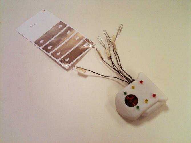
Conductive Ink Toolkit Physical UI
The Arduino device was programmed to then work with the different components created by the user. The interactive portion was created by using three different colored LED lights that are connected to the Arduino. When the user touches one of the conductive ink components, the designated LED lights up accordingly.


Buttons
Reading – Radio Buttons
The first application of conductive ink was using it to produce radio buttons. We developed a paper tool for the reading exercise by placing components that would work as buttons. The Arduino reads the capacitance of the circuit to determine which button is being pressed. The range of capacitance for each button was hard-coded into the Arduino. The layout is functional. However, we later discovered one major drawback of this layout: the capacitance changes from person to person.
Games – Potentiometer
The second application was using it as a potentiometer. We envisioned it to be for gaming purposes, where users can swipe across the paper component to play action games. Again, the Arduino utilizes capacitive sensing to detect where a person’s finger is between two pin sensors.
Writing – Circuit Completion
The third application was circuit completion. The writing library we provided in the program can be used to make paper tools for spelling exercises. The front of the letter cards show the letters to use to create the words, and the back of the letters, when arranged correctly, will complete the circuit and light up the LED.
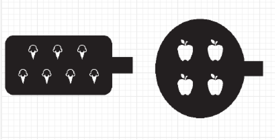
Arithmetic – Cutting Buttons
The final application is cutting. This idea was developed based on our theory that the area of a conductive image and its resistance would have a one-to-one relationship, and the value of one would be predictable when another was given. We planned to use it to produce paper tools for arithmetic exercise, where students would cut a pie of conductive image into smaller pieces. For instance, when students are asked to provide half of the apples, they will cut the pie image in half and connect it to the Arduino. Unfortunately, we did not discover a meaningful relationship between the area and the resistance to make this tool functional.